PEG® Design
The revolution in the field of PV substructure
PEG is an EW ground mount design that is high-density, lightweight, highly robust substructure with rapid installation and greatly reduced CAPEX. The design of PEG is fundamentally different from other substructures. It was re-designed from the ground up. Instead of heavy steel posts, many lean rods are used. The PEG design saves approximately 75%+ of steel compared to conventional substructures.
The aerodynamic characteristics of the flat structure close to the ground result in a significantly lower lift at high wind speeds. The lightweight substructure allows for shallow foundations that can be installed rapidly and safely with a convenient, waist high working height. No heavy machinery is required.
It‘s not EPC, it is EPI
Engineering-Planning-Installation
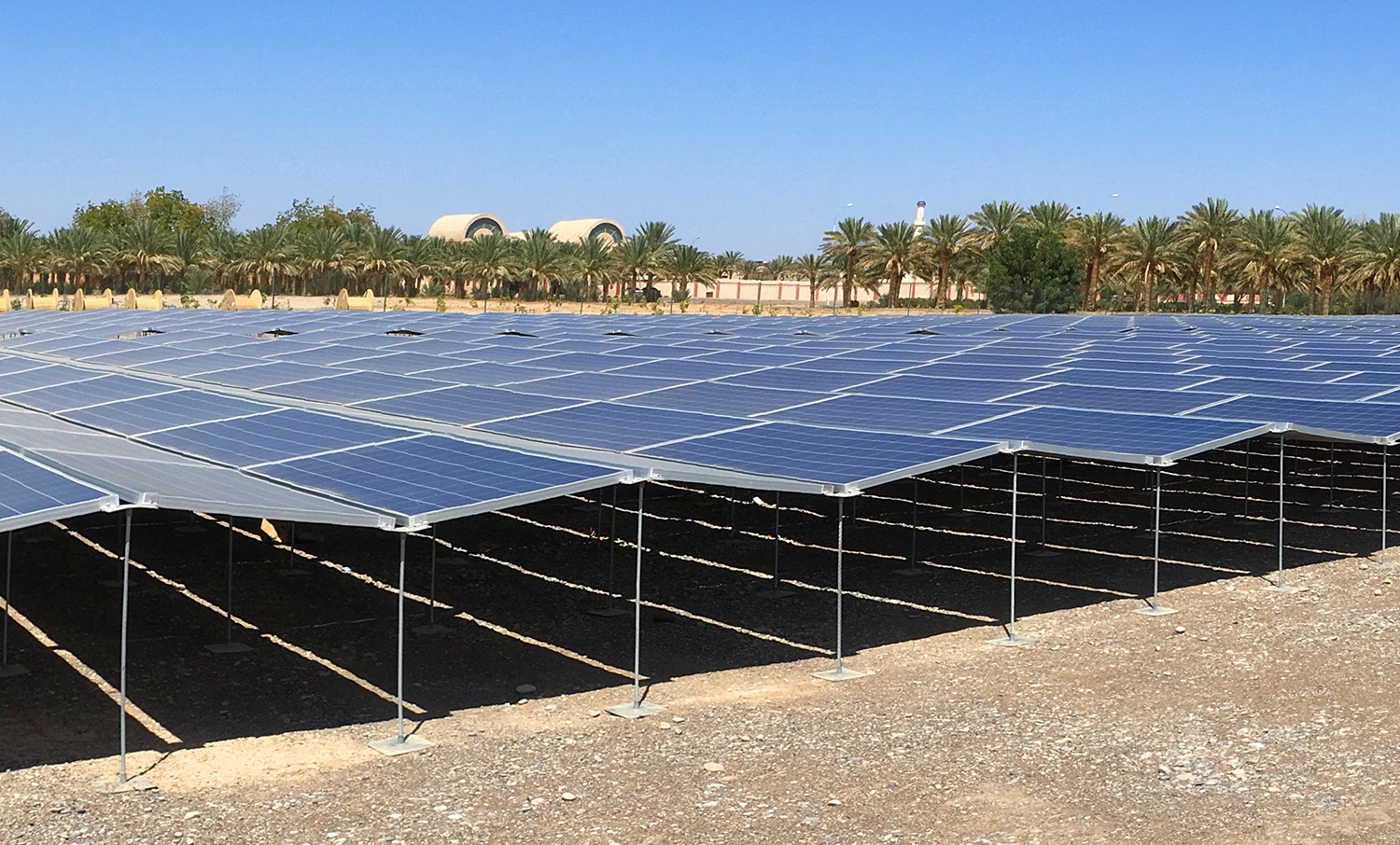
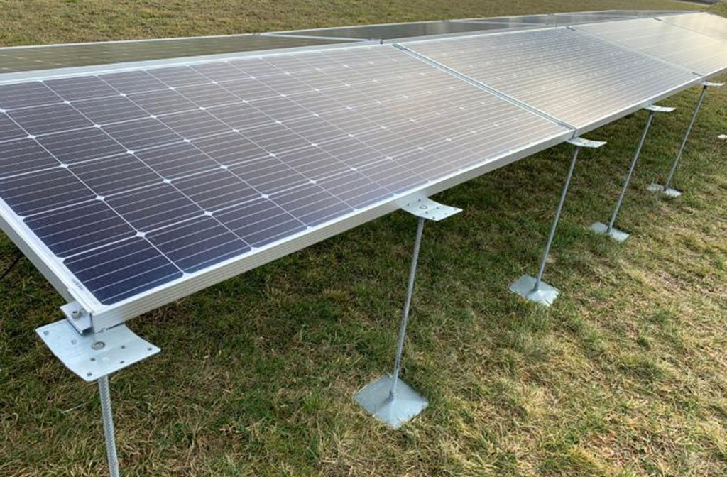
The PEG power plant will be installed rather than constructed. It is based on an innovative system design, which follows the ground surface – the PEG mesh. The ground-nailed substructure clamps the PV panels at about one meter elevation over-ground.
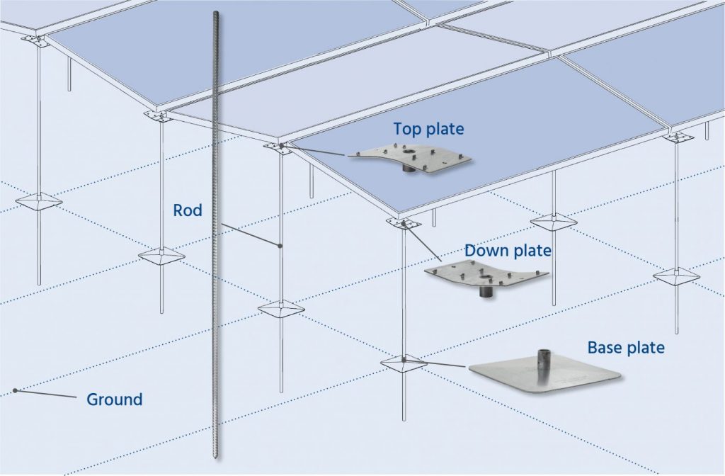
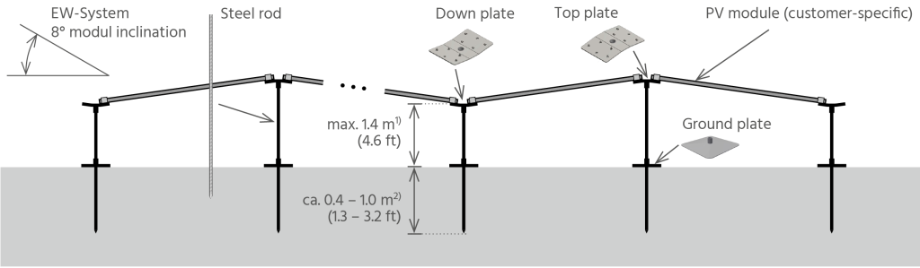
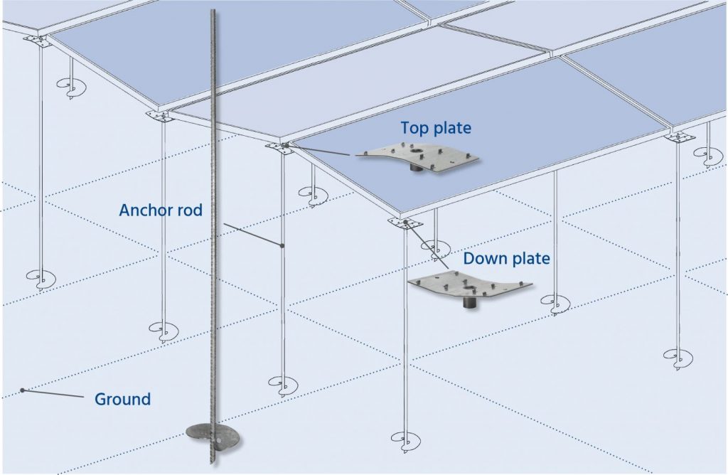
The specially engineered construction design with its flat ‘wave‘ pattern is very durable against environmental impacts. Furthermore at high wind loads the patented construction produces a down-lift, which increases the static characteristics. The patented construction consists of only three main components:
1. Rod
2. Ground plate
3. Top and down plate
The PEG System is a revolution in the field of mounting solutions for solar power plants with framed PV modules. It is unique and specially designed for east/west exposition. Due to the lightweight construction, no foundation is needed. Less material and a simple design lead to reduced labor costs and the phase between planning and commissioning is reduced significantly.
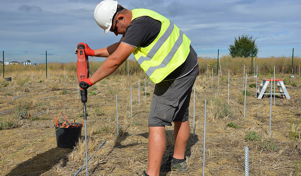
The PEG substructure is the lightest, most efficient and innovative system on the market. Substructures of our competitors are much heavier and more expensive. Most of them need concrete foundations and heavy machines. With PEG, the steel rods of the PEG substructure can also be installed with only a hammer drill.
Standard Ground Plate Version
These are the standard main components for most soil and load conditions. The components are made of galvanized steel.
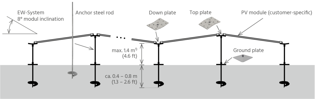
Anchor Rod Version
We recommend this version for low ramming depths (e.g. former landfills) or or very soft soil.
2) For exceptional permafrost conditions, the ramming depth could be up to 2m, done by the use of two rods crimped together onsite through a sleeve, subject to project-specific approval.
PEG® with additional support for high wind and snow loads
The HL (High Load) version of the PEG included additional support under the middle of the long edges of the modules, to withstand high loads at sites with extreme wind and show. This design includes two version, HL Snow and HL Wind. Download data sheet for more info.
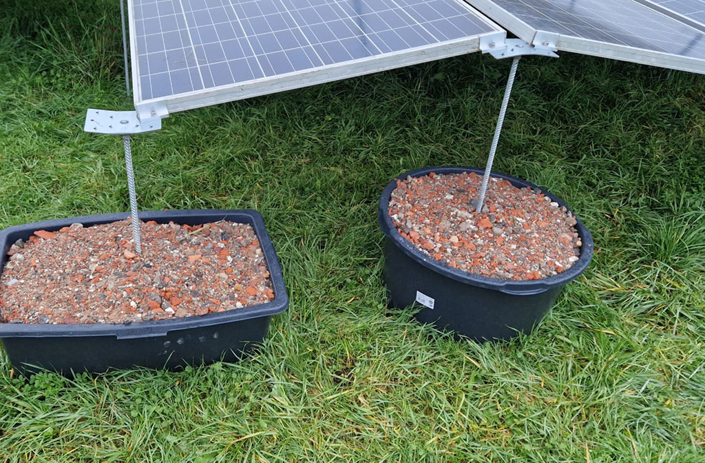
PEG® EW Ballast Design
Plastic mortar tubs or high density plastic plant pots, one per rod, are filled with recycling material as a cost effective ballast solution for the PEG System. The plastic tubs are available in different shapes and sizes , eg round and rectangular, which should be evaluated based on the required amount of filled material and the required gaps between the tubes for access under the PEG for O&M activities. Download data sheet for more info.
System’s Height & Foundations
No foundations required. The rods are rammed into the ground
Ramming depth concluded based on pull-out tests & soil type
Minimum ramming depth required for short & long rods: 500 & 650 mm
Typical ramming depth is ~650-750mm, rarely exceeded 800mm
Above ground height of short rods: 850mm (higher TBD per project if required)
Special anchor rod available for shallow ramming (500mm) or very soft soil
PEG® Engineering
Clustering PEG® power blocks
The whole engineering process has been simplified by a clear standardization with PEG® system blocks. Related to PV panel type PEG® engineering process works with pre-defined power blocks.
The folowing movie is an example of a PEG® solar power plant, built with 90 blocks (each 570 PV modules) on 11.99 ha (29.63 acre). The result is 1.7 MWp/ha (0.7 MWp/acre):
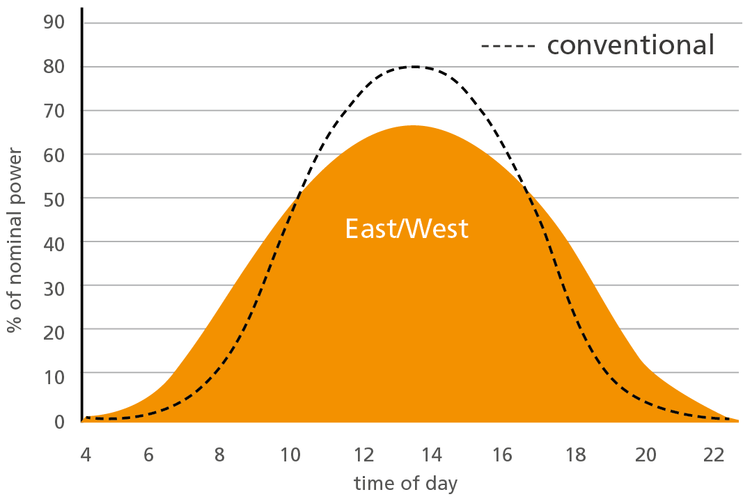
More consistent performance
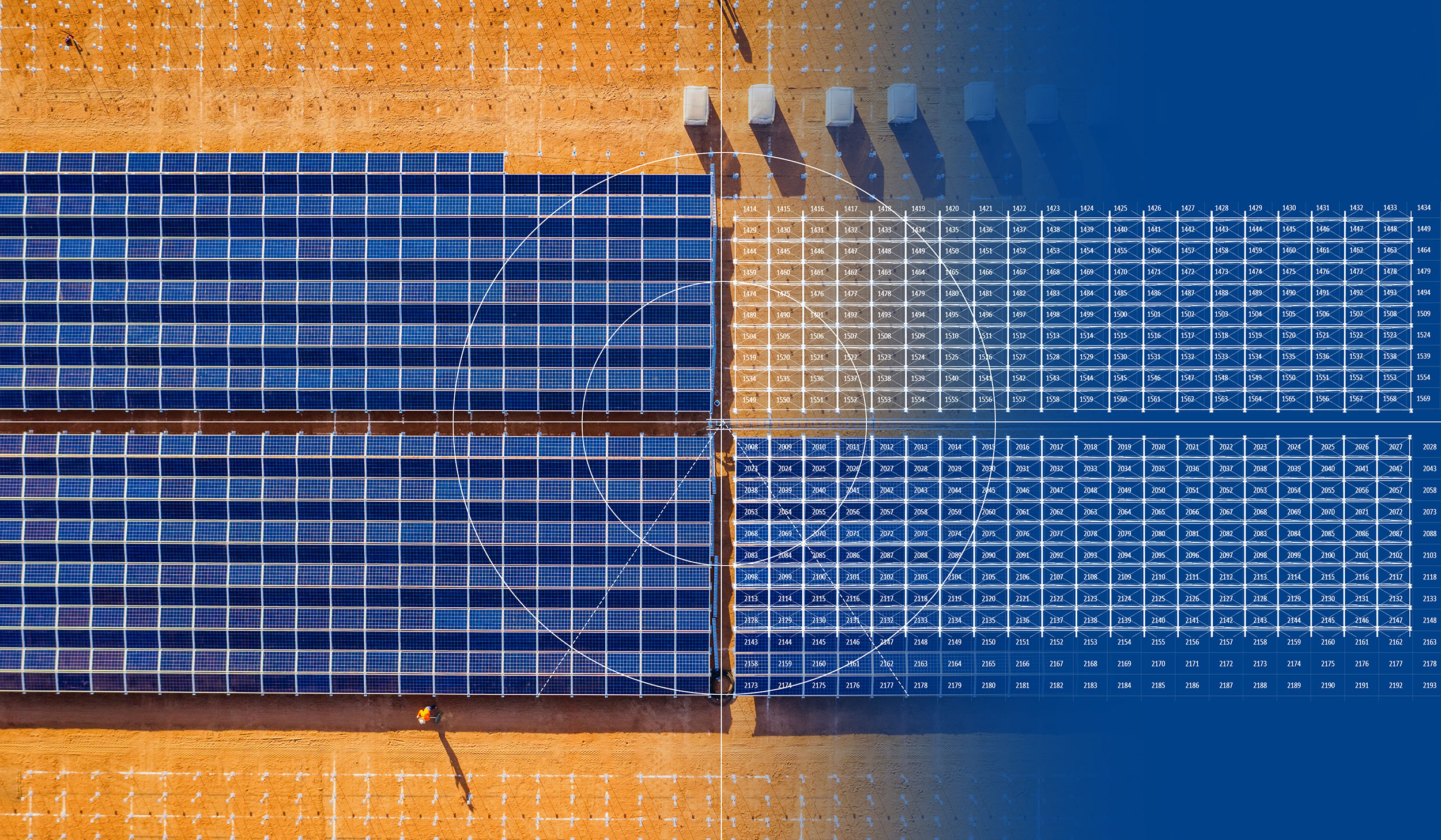
In contrast to conventional PV module lines, the PEG system utilizes a greater power-generating photovoltaic area.
The flat and east-west oriented PV generator creates a smoother daily averaged electricity yield.
It is very simple to make something complicated,
but really complicated to make something simple.
PEG® vs. Conventional Mounting Systems
| Comparison of: | Traditional Solar Power Plant | PEG Power Plant |
|---|---|---|
| Raw materials | High amount of steel, wood and concrete | No concrete, no wood; saving up to 78% steel |
| Area utilization | Medium, cause system-related free space between straight PV module lines | PV module mesh with highest area utilization, 225% increase in MWh/acre versus trackers and conventional fixed tilt systems |
| Project process | EPC: Engineering, Procurement, Construction over several months | EPI: Quick Engineering, Procurement and Installation over a few weeks |
| Engineering | Limited layout design due to shading concerns | Standardized PEG clusters offering flexible layout design without shading concerns. |
| Procurement and logistics | Individual planning and components » complex transportation planning, customer duties and logistic efforts | Cost-effective process, transport planning and logistic process by container-based units |
| Installation | Heavy machinery, elevation platforms, skilled labour and high number of man-hours required. | Much simpler process with hand tools, smaller teams and mostly unskilled labour; without the need for heavy machines, elevation platforms and cables trenching. |
| Operation & Maintenance | Elevation platforms required, trenching for undergrown cabling typically required | Installation on ground level without a need for elevation platform |
| Energy yield | Peak power generation at noon time | Balanced power generation with better energy yield at sunrise and sunset due to east/west exposition |
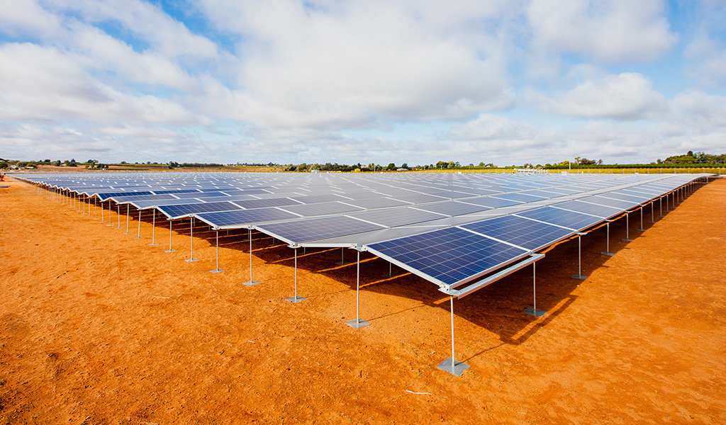
Example: Comparison of a Tracker System vs. PEG®
Same location, same area in North South Wales, Australia
![]()
![]()
Plant system rating of solar tracking system is 7.00 MWp:
PEG® has a system rating of 20.52 MWp on the same construction area:
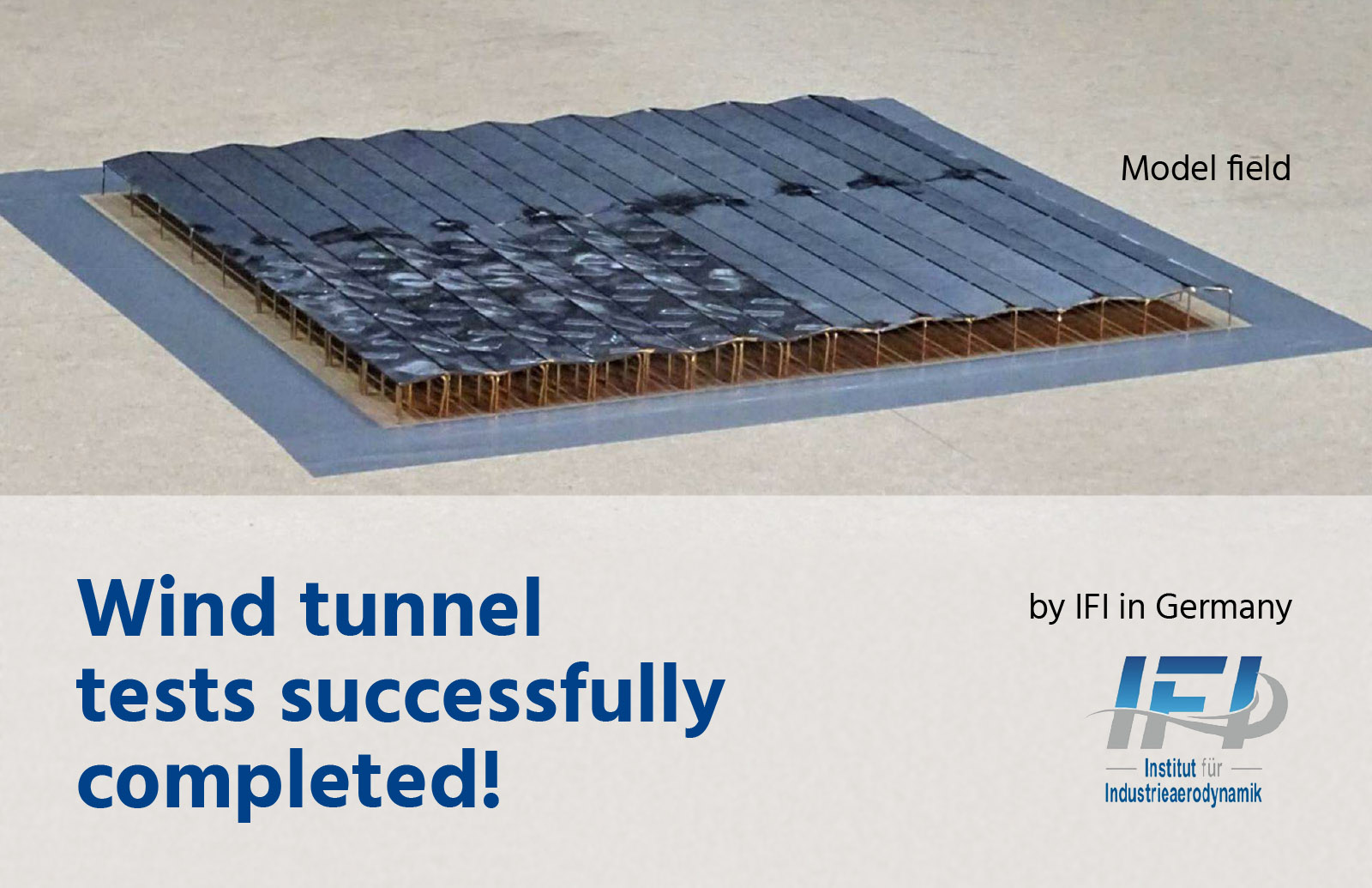
Design Robustness of the PEG® Mounting System
- Wind Tunnel tests successfully completed by IFI in Germany
- Max wind speed (ASCII 7-10): 185+mph (298+ km/h)
- Max snow load: ~50PSF (Pound per Square Foot) *
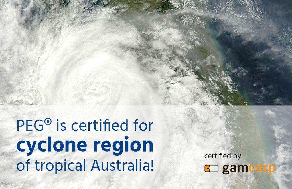
- Compliance in tropical regions (eg wind regions C in Australia)
- More than 100 PEG solar power plants have been built worldwide since 2012.
There have been no problems with the stability of any of these systems.
Download reference list - The Atmospheric Category (Corrosion Classes) is defined per site based on the local code, eg the proximity to the ocean
- PEG suitable for up to Corrosion Classes C3 (ISO 9223), or the equivalent local code. C4 might be approved, evaluated per project
Is the PEG system robust?
The PEG design allows free airflow in and out of the space under the PEG, keeping the temperature low
PEG® Technical Data
| Technical Data PEG® | |
|---|---|
| Orientation PV array | Patented 8° East-West, fixed tilt, aerodynamic proofed (patent-registered design) |
| BOM (Bill of material) | 1.105 rods and 2.15 clips per module |
| Durability | Hot dip galvanized steel rods and pre-galvanized steel plates. PV modules and clips based on corrosion-free aluminum and glass. All DC cabling components are weatherproof and UV resistant. |
| Wind loads | Max wind speed (ASCII 7-10): 160mph (257km/h) |
| Approved ambient temperature | Up to 50°C / 120°F (up to 55°C / 131°F with Hot Climate Option) |
| Certifications | Clamping approval from module manufacturers. Wind load certificate by local engineering firm in accordance with local wind codes. The PEG substructure is UL certified. |
Sales

Henner Jahnke
Chief Sales Officer

Herbert Heidel
Europe, Middle east

Matthew Lusk
North & South America, Caribbean

Amit Chheda
Rooftop & cabling - Asia, India

Yoni Ben Mazia
Israel, Australia

Abhishek Deshpande
Strategic Business Development Manager
Internal Sales Service & Project Management

Andrea Vidoni
Worldwide

Sabrina Klippel
Worldwide
Pictures: Jurchen Technology GmbH, Meralli Projects PTY Ltd, Belectric GmbH, Volta Solar BV, WikiImages, IFI