PEG®
Info for Project Developers
PEG® benefits for solar project development
The PEG® racking solution is extremely unique providing exceptional benefits for project developers in all development aspects:
- Far more flexibility with securing land
- Far greater chances of community support
- Far less council & environmental permit risks
- Securing project investment
The above are achieved through the following characteristics of the PEG® system:
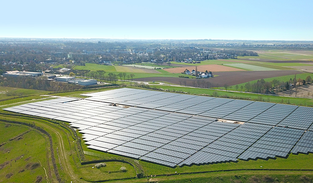
- Extremely high land use, of ~750 kWp per acre (~1.85 MWp per Hectare) assuming 550W modules
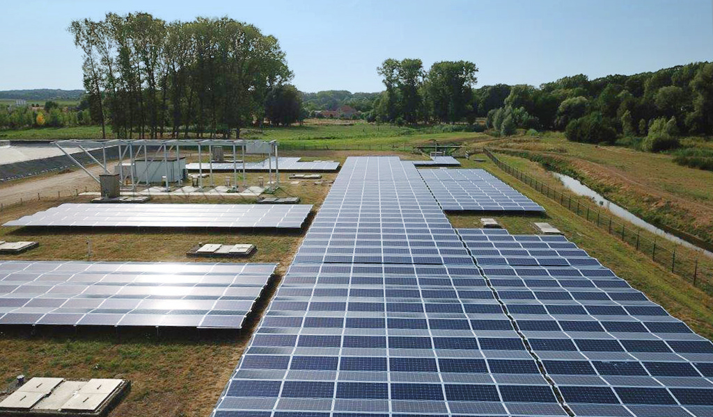
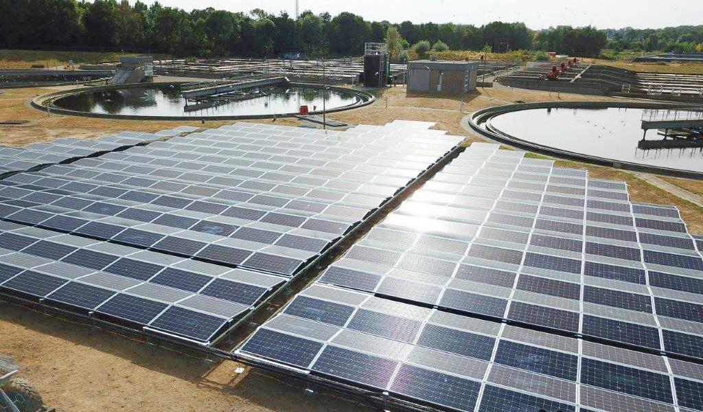
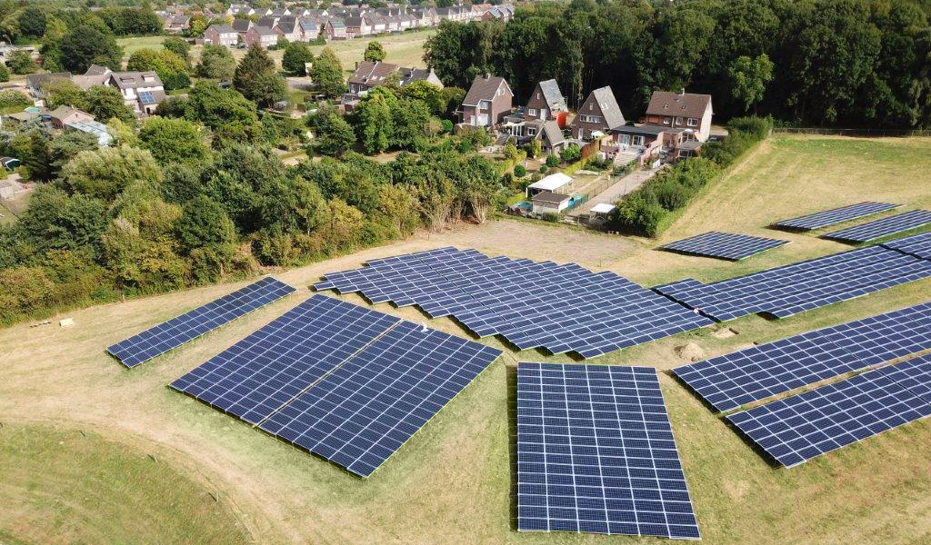
- Very low visual impact, ~3.3ft (~1m) above ground
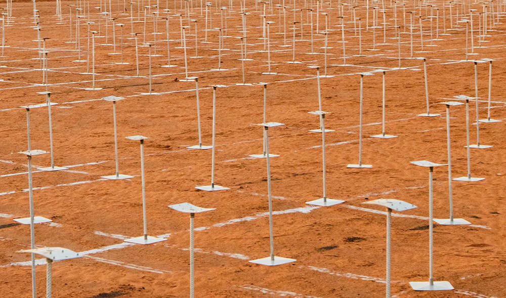
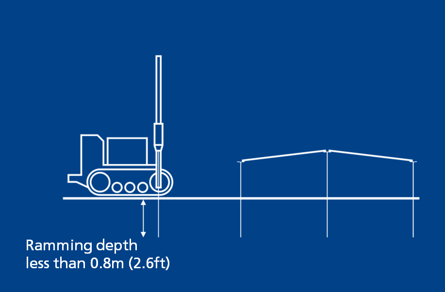
- Very shallow foundation depth, between 1.5ft (0.5m) and up to 2.6ft (0.8m) below ground, with no impact due to soil upheave in frost conditions!
- Improved sustainability, with far less carbon footprint and land use vs other systems
- Very low CAPEX, due to far lower supply and installation costs leading to a financially viable project
- Bankable solution, with over 400 MWp installed worldwide and DNV-GL bankability report issued


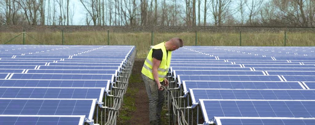
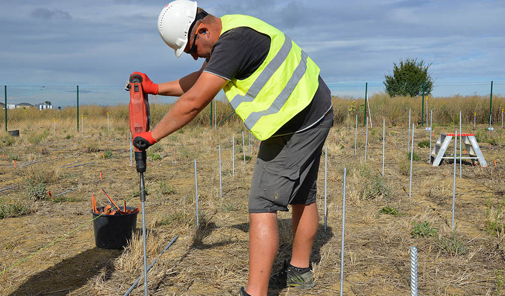
Picture: Installation of DC cabling at the PEG solar power plant in Lembruch, Germany. Commissioned in 2018.
Securing Land
Securing land near a location with sufficient electricity grid capacity is a complicated task, which imposes great hurdles during solar project development.
PEG® significantly increases the site´s selection flexibility and reduces risks due to the following:
High-density racking that allows a 97% GCR ratio and ~225% higher land yield (per acre or hectare) than trackers and fixed tilt systems
Project is still feasible when parts of the land is not usable, eg. due to existing infrastructure, land slopes, water channels
Maximize value for money in areas with expensive land costs close to an ideal grid connection point
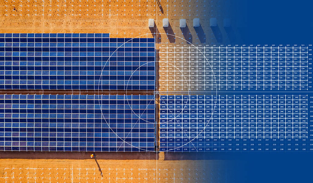
Layout example ~3 times more DC with PEG® vs Tracker:


PEG® solar power plant | Mesilot – Israel
The extremely effective land use of the PEG® system allowed the development of this project, which otherwise would not be possible.”
Shahar Ben Moyal, CEO Meshakim Partners Mesilot Solar Farm, 4.6 MW Israel
Mesilot Case Study: Request form
Community Support and Local Council Permits
Community acceptance, neighbors consent and council permit approval are critical for any projects, especially on land near residential or industrial properties.
The PEG® significantly decreased those risks due to the following:
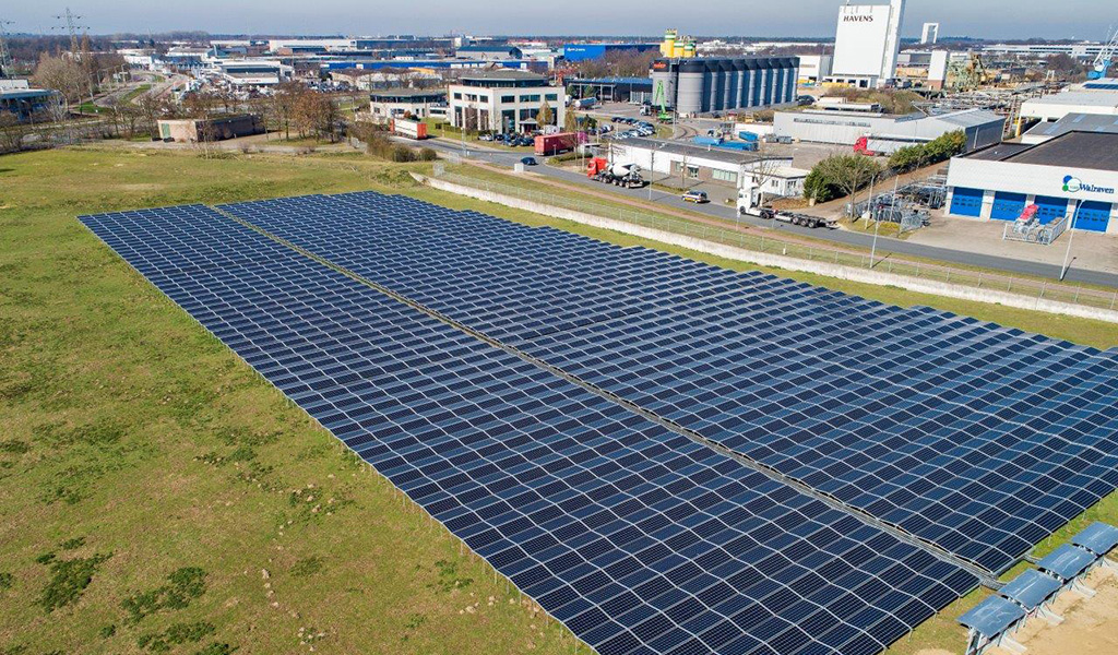
- Significantly reduces visual impact (height ~1m (~3.3ft) above ground)
- Easily blends into the environment
- Easily concealed by low profile vegetation
Shallow foundation of less than 0.8m (2.6ft) without concrete
- Reduces council permitting and environmental risks
- Reduces risks of landlord’s refusal due to fears of decommissioning at the end of project life
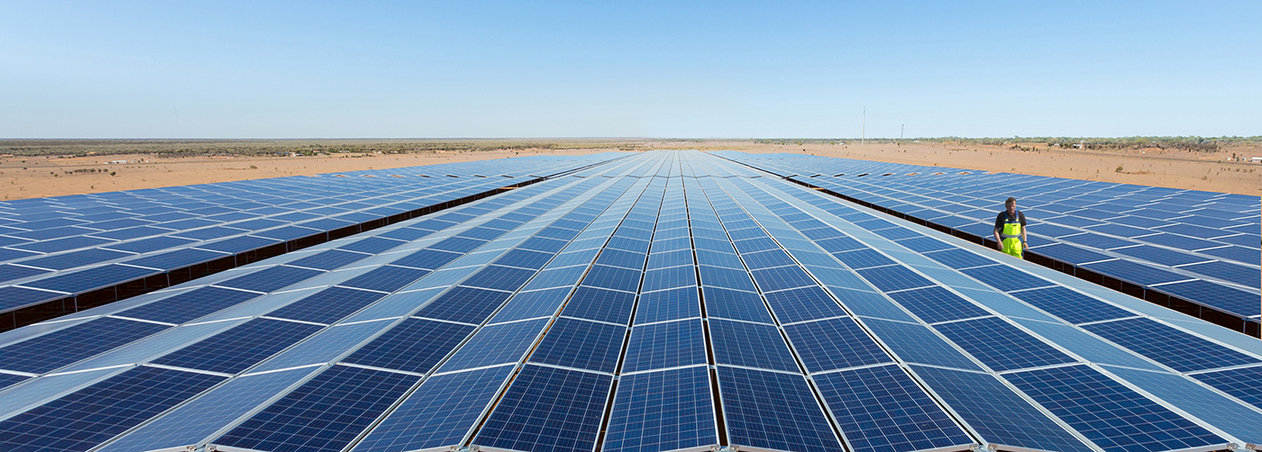
PEG® solar power plant | Dareton – Australia
Due to the extremally efficient land use of the PEG® system and the flexibility of the PEG® blocks design we were able to come up with a cost effective design, which minimized the site preparation works.
Rob Mailler, Managing Director Kinelli Pty Ltd.
Dareton Case Study: Request form
Securing project investment
Lightweight and simple PEG® racking design allows significant CAPEX savings
- Reduces required equity investment
- Enables a more financially viable project
This is achieved due to:
- Major savings in material supply, delivery and logistics costs
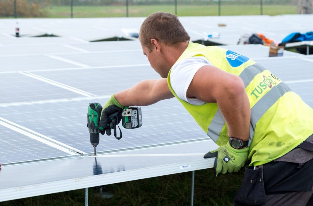
- Significant saving in labor hours required to install the system
- Only low-skill labor required, which reduces the labor hourly rate
- CAPEX optimized by placing DC system where fewer or no site earthworks preparations are required
- Major savings in machinery and tools with only hand tools required for installation (no heavy machinery) eg for concreting, trenching and carrying heavy parts, which reduces both mobilization (even more on remote areas) and installation costs
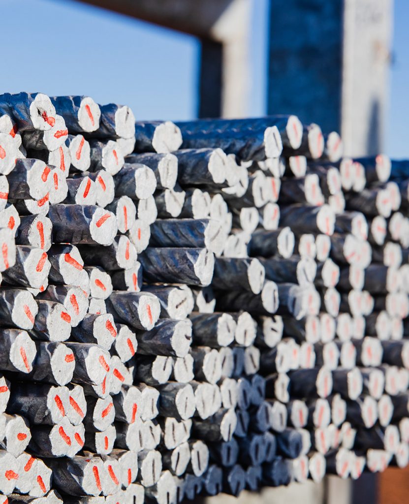
- No concrete or sand required for the foundations and no DC trenching
- Smaller risks related to infrastructure underground due to shallow foundations
- Projects in unionized/expensive labor markets are more feasible
- Bankable solution with extensive bankability report provided by DNV GL
- Bank financing secured for pre- and post-financing on projects in Australia
- PEG® tested design with assets in the field since 2012
- No warranty claims on all installed PEG® solar plants so far (more than 400 MWp installed)
- Long company history of German engineering excellence with over 3 GW of DC cabling and 2.6 GW substructure assets utilized on solar plants and over 700 MW under construction
Bankability report: Request form